


RaceCal 'Tech Insight' - Sequential Gearbox Control Part 2
Welcome back to part 2 of our sequential gearbox 'tech insight'.
You may remember that we classified our previous article as an entry level closed-loop implementation; this does mean you can take the process one step further. The extra step you can take is by removing the manually actuated shifting mechanism and moving to a paddle shift setup.
The previous article focused mostly on the Syvecs system; this article will focus mostly on Cosworth’s implementation as it is the one I am most familiar with. If Romain was writing this it would be the other way round!
A paddle shift setup has two steering wheel paddles - one for an upshift, and one for a downshift. The paddles signal to the ECU that the driver is requesting a shift – nice and simple, you say? Well, you do require quite a lot more hardware, and further calibration once again!
So this time, what you'd need in addition to our entry level implementation if using an air powered system such as Shiftec or Geartronics (you can remove the load cell FYI, but the rest needs to remain):
- 2 x Steering wheel mounted paddles (up and downshift request)
- Air powered gearbox shifting actuator
- Air compressor
- Air accumulator inc. pressure sensor
- Shift valves (2 x – up and down)
- Detent, clutch pressure and mode switch (optional but recommended!)
Steering wheel mounted paddles
These can be fairly basic switching paddles that will switch between 12v/GND or open circuit when 'open' or 'closed' to signal a shift request to the ECU. These can either be hardwired direct to the ECU, or through a steering wheel mounted CAN switch board (Cosworth CSB for example) to transmit the shift request to the ECU over the car's CAN network. The safest method is to hardwire in case of CAN failure or errors on the bus. The Cosworth CSB does, however, use a validation sequence that is transmitted to the ECU to ensure no incorrect triggering.

Air powered gearbox mounted shifting actuator
In the previous example you would pull/push the gear lever, which in turn pushes or pulls a cable or rod to drive the shifter mechanism on the gearbox. With a paddle shift setup you would change this to an air powered actuator mounted directly to the gearbox. The actuator can exert massive force in a very short period of time to automate the shift extremely quickly.
Whilst this article focuses on an air powered system, you can also use electronic based actuators from the likes of XAP or Megaline.
Air compressor
This component creates the compressed air required to drive the gearbox mounted shift actuator. The compressor will usually be powered via a PDU or relay with one of the ECU's PWM outputs, enabling the relay for the compressor to turn it on and bring the pressure up as needed.
Air accumulator inc. pressure sensor
This stores the compressed air which the compressor has created and feeds it to the shift valve solenoids. You want to run a pressure sensor in the accumulator so you can request the ECU to trigger the compressor to maintain a constant pressure. This is traditionally around 8-9 bar (a 10 bar sensor is a good choice). Anything below ~7 bar pressure and the ECU will enable the compressor to bring the pressure back up. This is all user configurable of course.
Below is an example of how this looks in a Cosworth ECU - you will see settings to set up the pressures, pump priming, voltage limits etc.

Shift valves
The valves/solenoids are fed compressed air from the accumulator. These valves are wired directly to the ECU outputs and will be enabled when the driver requests an up or down shift. The solenoid essentially allows compressed air to reach the correct port on the shift actuator to drive the shifting mechanism in the gearbox.
You will wire these much the same as a boost solenoid. 12V to one side (current draw is very low ~0.4A) and the other side to an ECU PWM output.
In the ECU you will be able to select the valve frequencies etc.
Detent, clutch and mode switch
In our opinion, one if not all the above switches/sensors should be fitted when moving to paddle-shift.
The detent switch is a safety switch that will inhibit shifting from say 1st>N, N>R, N>1st etc. unless pressed. Wire in a momentary Otto P9 switch or similar and assign this in the ECU. There would be nothing worse than shifting down the box and going into and past neutral when going into that 1st gear hairpin! Engine damage will be imminent and this can happen in the heat of the moment.
The clutch switch or clutch pressure sensor can be used in combination with the detent switch. Again, this is in place to save you from mistakenly selecting the wrong gear at the wrong time.
You will see here in the Cosworth system how the Detent and Clutch switch will be used:

The final part is a 'Mode' switch. This is used mostly if part of the shifting hardware was to fail. Due to the safety strategies in modern ECUs, in most instances if a component fails the ECU will not allow the actuator to shift. If this happens at an inconvenient time (i.e. anywhere other than the pit garage), the use of a mode switch allows you to override the gearbox control and control manually.
You can have a simple toggle switch to select two options, or in the below example you can use a rotary switch to change between the multiple options available.

With the system fitted, this is how it all goes together:

The diagram is hopefully self explanatory, however below is a written walk-through of the process when your system is installed and inputs/outputs assigned in the ECU:

With the system fitted, this is how it all goes together:

The diagram is hopefully self explanatory, however below is a written walk-through of the process when your system is installed and inputs/outputs assigned in the ECU:
- Power up ECU, ECU will perform its usual start-up checks.
- ECU will read accumulator pressure from the sensor and report back to the ECU.
- If the accumulator pressure is low (i.e. under 7 bar), the ECU will 'enable' the compressor to bring the pressure up. You can wire this to a relay and enable the compressor on the low side, or to a switch input on a PDU to drive the logic to power the compressor. Traditionally this pressure is between 8-9 bar. Above this the compressor will turn off; below this the compressor will turn back on.
- In neutral, the driver will depress clutch, hold the detent switch and pull the upshift paddle.
- ECU will see the request, and ground the PWM output the upshift valve is on.
- The valve will then bleed air pressure to the actuator which will in turn move the gearbox ratchet mechanism to select first gear.
The above is an overview of the diagram - there will be considerably more steps/checks the ECU will monitor before allowing a shift.
Once tested, you can move on to the calibration of the system. Calibration parameters will be similar to those discussed in part 1, as regardless of the shifting mechanism, you will still need to reduce engine torque to unload the dogs to allow the shift.
With paddle-shift control, a large part of the calibration is correctly setting up the extra safety that is in the ECU's gear controller code.
As you will see in the examples below, there are multiple safety functions there to reduce the chance of damage to your gearbox or engine.
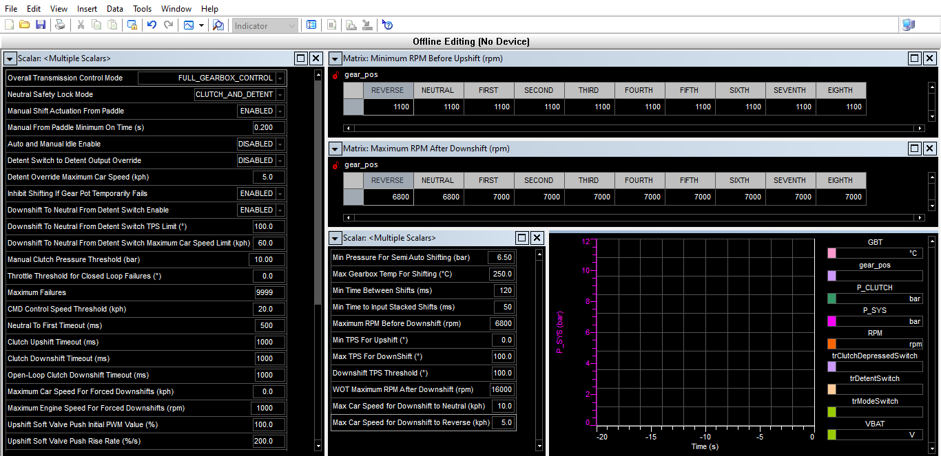
This allows limits, or for the ECU to deny shift requests based on detent switch, clutch pressure, accumulator pressure, car speed, rpm limits after downshifts (you don't want to downshift too early and end up at 10,000 rpm!), TPS angles, timers and much more. We would be here for weeks explaining them all, however hopefully this screenshot gives an idea of what's available in an ECU with a proper gear controller onboard.
We did get a question from our last article in regards to a downshift cut, rather than just a ramp out, and when you'd use this.
The reason why you may want to induce a gear cut when downshifting is if you were to be on throttle. Whilst you may not want a down shift at 90 deg TPS angle, if you are on partial throttle, say 20 deg, and want to quickly downshift, the ECU will cut to allow the dogs to unload and for the shift to complete. This allows you to shift without having to remove your foot from the throttle to reduce the torque manually.

Another use is fuel/ignition cuts being used in the ECU's 'Anti-Push' strategy. The ECU will control fuel and ignition, so when you request a downshift (once calibrated correctly) you won't get a sudden lurch forward as would happen if the engine was still producing torque when the throttle is blipped.

This concludes our insight into sequential gearbox control - we hope you have liked the two articles; if you'd like to learn more about this subject or any other for that matter, please email rob@racecal.co.uk with your questions and requests!
Please note all calibration parameters shown in the screenshots are for example only, these are not calibrated figures to use when running. If you require assistance with suitable figures please get in touch with us directly.